Sunday, 27 October 2019

Bevels and fitting the side plating.

I roughed out the bevels using a power plane and finished up using a hand belt sander. It is not all done yet, some fine tuning is to be expected before I permanently affix the plating.


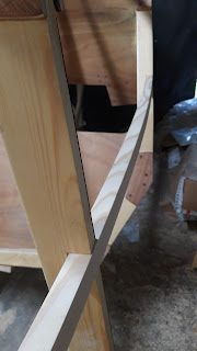
I used a straight piece of board to check the surfaces while bevelling the longitudinals. After a few iterations the sides are ready for fitting the plating. In the picture below frame B with the curved side futtock. the additional 3mm in the centre makes for a nicely flowing curvature of the hull in this spot.


Fitting the large sheets of plywood was a bit fiddly by my lonesome, but quite manageable. I fitted one side, cut out the shape, checked that it fits the other side (should be symmetrical) and cut an exact copy for the other side. The offcuts may be large enough for the waterline strake somewhere. The Designer claims they are, I'm not sure, they seem to just fit. Hard to say without the rest of the bevels at least roughed out.


It is now too cold to glue everything together, so I'll wait for more favourable conditions. I want to have the sides fully plated before trying to fit and glue in the remaining chine logs. They require large forces to bend and twist them into shape, especially around the bow section and it might be tricky  to keep everything from shifting again. With the sides fastened, nothing will be able to move or twist anymore. The geometry as it is now is as good as I ever could wish for, so why risk ruining it.
Tot de volgende keer.


Installing the longitudinals.

Cutting slots for the stringers, located in the middle of the futtocks, is kinda easy. After placing the stringers in the correct location I cut alongside the beam to get a proper angle. Also I marked the depth on the saw blade. Easy enough.


An oscillating multitool came in handy for gouging out the bottom of the slot. I eyeballed the approximate angle.


 Whenever the stringer needs to twist (which is everywhere) a wrench made out of scrap plywood makes for a good helper:


Easy, right? NOT. I rushed it again, apparently, and some of the slots came out loose. Not a big deal, in the end I shimmed them and filled the remaining voids with thickened epoxy. Should be good enough, but some of the loose slots will be visible inside the cabin. Ah well, that's life:


I fastened the glue up with temporary fasteners (regular steel stax screws with a shank, stainless is too weak if you want to be able to remove the screw for whatever reason after the resin cures, I've had my share of twisted off heads, as described in one of the previous posts). Does not look very nice, but it does not have to. After removing the stax I'll either drive in a permanent screw and/or glue in a trennel.


The sheer clamp (the chine log at the deck joint): some slots came out perfect, some of them, well, were a tad too large, resulting in a 5mm gap in one place. The joint with goop oozing out (below) is the one i mean. I may decide to cover them all up with larger fillets thickened (coloured) with wood dust to make them match the darker gussets. Or just leave them as they are as a reminder: Measure twice, cut once. Not the other way around...


The stem situation turned out better than expected, and based on my experience so far I had pretty low expectations. Due to the heavily bent longitudinals pulling from all sides, each with a slightly different force the stem did move from it's intended location. Luckily it only moved on the deck side and only by about 3mm. At the waterline the shift is zero. I could have let it be, 3mm is nothing compared to the dimensions of the boat, but I compensated nonetheless by removing 2mm of material from the starboard side of the stem just so that the forestay chainplate does not look off centre when everything is ready.


Below some more pictures of how it turned out:


Next step: bevels and plating!

Tuesday, 22 October 2019

Electronics

As for the electronics - some are allowed by the class rules, like a simple GPS etc. I've started assembling a prototype navigation and monitoring system out of:


  • A microcontroller (atmega328P, for now in an arduino pro mini package, maybe i'll go for a standalone 328PB for the additional UART pins, not sure).
  • An ESP32 board for an optional wifi interface - a colleague insists I drop the 328 in favour of the MC on this board, not sure about that...
  • An absolute orientation sensor (Bosch BNO055, a bit pricey, but looks to be worth the price), that includes a compass and a heel sensor, so more things will be possible like heel corrections etc. Maybe even accelerometer data could be used to estimate the stresses on the hull...
  • A NEO-6M GPS module, cheap, but should do the job. Thanks to the price (few bucks) I may include 2 or more for redundancy.
  • Some simple low power LCD display for displaying the basics: a 20x4 text display should do. Problem is that would be the only component that needs a 5V power supply (the rest is 3.3v), so maybe even some logic level shifters would be necessary - all that eats power... maybe i'll find a 3.3v display. Or use one of the many well known workarounds...
  • Some EEPROM for logging with some power hungry fallback like an SD card reader.
  • I don't exclude the possibility of integrating a raspberry pi like solution for a chart plotter and a fancy human user interface. That however would be optional, depending on available power.
  • Possibility to hook up an anemometer, maybe some other sensors, definitely water, air and hull temperature.
  • Not sure how I feel about trying to integrate an NMEA bus for future upgrades, seems like overkill power consumption wise, probably will stick to I2C, UART and some analogue inputs.

Power source will be a (small) lead acid battery and a small solar panel to keep everything topped up.
I want to keep everything modular and low power, so i'm not sure about the power supplies yet, probably a buck converter for everything but the GPS module which might require a clean power source like an LDO regulator. We will see. In the end I want the basics of the navigation system to be able to operate on a 9v battery for a significant amount of time if need be.

In the picture below some of basic components i'm playing with:


All of the above is well supported software wise, so that is quite easy. After the physical layout and firmware are kinda ready i'm either gonna solder everything on a perforated prototyping board or order a proper PCB if I feel like making a PCB design.
Also not sure about the housing for all of this: plastic or wood, convenience or style.
Tot de volgende keer!


Sunday, 13 October 2019

Stem. Again.

After having a  closer look at the drawings, in particular at the stem I decided I screwed up and made the laminated pine too thin and the wrong profile alltogether. In my defense the drawings are a bit vague on the exact shape of that particular piece.
While in Germany tending to other business, pillaging through the timber section of a large German hardware store, I found some perfectly dimensioned boards of Douglas fir, a well known north american species valued by boat builders for good rot resistance, strength-to-weight ratio and it's ability to hold fasteners (I think). All in all a good deal, especially since the reddish color will match the okume plywood way better than the pine board ever could.
So, I brought back three boards and cut out what I think will be a much better stem. I will make a deadwood and a stem cover out of the remaining 2 boards. Here's how it looks like next to the old one:

BTW, I managed to cut it short by 15mm on the deck side... not a big deal, but still annoying. For some reason adding 90mm to 90mm  resulted in 160mm, in my head that is. I feel more and more errors will be creeping in, so I'll slow down a bit. And I'll use a calculator from now on.

That is now done and progress is being booked in the area of fitting the longitudinals. I have stated in a previous post I believe it will be much less time consuming, easy even. Boy, was I wrong... I will give an update once the first batch is all glued up and ready to be plated. For now it looks like this:


cheers.

The tent is back

Finally the workshop stands again. After a lot of busywork and other projects I finally managed (with some help) to prep a place for the ten...